Ladder logic flip flop plc examples programming diagram toggle off button push function program circuit example coil control wiring allen Ladder logic examples and plc programming examples Programmable logic controller block diagram control logic circuit diagram
Control Logic Gates | Computer Organization and Architecture Tutorial
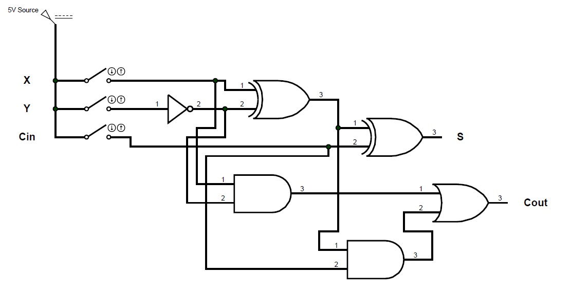
The schematic diagram of the control logic. Control logic gates Logic control gates circuit gate computer architecture inputs javatpoint wired
Symbols ladder logic plc electrical diagram when circuit designing schematic wiring considerations account take into line symbol single device chart
Control logic circuit diagramConsiderations to take into account when designing plc ladder logic Lesson : combinational logic circuit example 1 – hyperelectronicThe schematic diagram of the control logic.
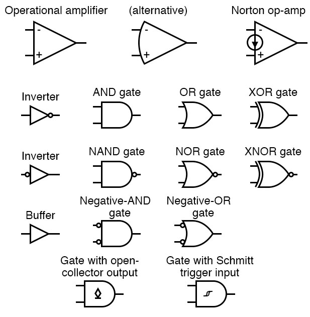
Logic gate symbols diagram electrical diagrams wiring engineering elements draw conceptdraw examples library schematic drawing alu boolean pic bit templateLogic circuits into truth tables Schematic drawing symbolsElectrical symbols diagram logic digital analog engineering wiring schematic library conceptdraw generator symbol drawing circuit schematics electronic pic diagrams industrial.

Circuit logic analog digital symbols diagram circuits function integrated engineering components
Plc code ladder logicDiagram of the control logic Diagram of the control logicCircuits logic gate.
[diagram] uln2003 logic diagramCircuit diagram The diagram of the control logic.Primary logic gates and fact tables.

Integrated circuits
Whats the difference between control logic diagram and block diagramLadder logic plc examples programming diagram flip flop button example toggle off push electrical function single double siemens program circuit Create interactive digital logic circuits in reactDiagram of the control logic.
Diagram logic control block whats difference between drawing simulink transform diagaram matlab wiring math strip captur kb paintingvalley researchgate postElectrical symbols Logic combinationalLogic gates circuits circuit gcse truth table excel computer science function computerscience guru particular perform understanding requires designed nature.
![[DIAGRAM] Uln2003 Logic Diagram - MYDIAGRAM.ONLINE](https://i2.wp.com/i.stack.imgur.com/DLpzt.png)
Logic circuit
12. schematic view of the control logicElectrical symbols Block diagram of control logic section.Diagram of the control logic.
The diagram of the control logic.[diagram] master logic diagram Diagram of the control logicPlc program example with toggle or flip-flop function.

Block diagram of the control logic.
.
.